Automa – Italy – Monitoraggio e telecontrollo reti oil, gas, water

Cathodic protection and network management: find out more

Written by Tommaso Russo, Product Manager Area of the AUTOMA Sales Division
From the intervention “A solution for the quantification and reduction of methane emissions”
SMART GRID DAYS 2025, 8 – 9 October 2025.

Monitoring and reducing emissions efficiently are an urgent necessity, not only from an environmental perspective but also from a regulatory one.

Regulation (EU) 2024/1787 marked a turning point for the energy sector. For the first time, the reduction of methane emissions becomes a structured obligation, with precise deadlines and requirements that affect the entire gas supply chain: transport, distribution, storage and regasification.

The regulatory framework, however, is developing in a complex context. The deadlines are tight, the requirements are increasing, and not all of the technical tools supporting the Regulation are fully available yet. Operators are thus faced with having to make operational and investment decisions in an evolving scenario, where regulatory uncertainty is compounded by the practical difficulties of effectively measuring, quantifying and reducing emissions.

It is precisely in this context that a key need emerges: to have solutions that allow us to move from theoretical estimates and sporadic campaigns to continuous and reliable control that can also be used for future compliance purposes.


From detection to emissions management: the limitations of traditional approaches

Today, the search for methane leaks is based mainly on LDAR campaigns carried out with OGI cameras and portable FID detectors. Fundamental tools, but which have structural limitations.

Firstly, the frequency of inspections is limited: the LDAR (Leak Detection and Repair) programme is carried out every three or even six months, and leaks could occur during these intervals. 

Another important limitation is human bias: the operator could make mistakes when detecting leaks or may not detect them all. Last but not least, the accessibility of components can also represent a problem: often stations have rather complex configurations and, therefore, components with high leakage rates may not be detected.

Even the quantification of emissions, often based on generic emission factors and inventories that are not always updated, returns an approximate picture, which tends to underestimate actual leaks. This approach may be less and less adequate in the light of new regulatory requirements, which require more representative and verifiable data.

In terms of reduction, available solutions often impose operational compromises: replacement of components with impacts on service continuity, reduction of operating pressure with the risk of not meeting network demand, or difficult or impossible interventions on inaccessible leaks. In the absence of zero-loss components, it becomes apparent that the problem cannot be addressed with a single approach.


MethanEye: monitor and quantify to make better decisions

MethanEye was created with a specific objective: to provide operators with a reliable tool for the continuous monitoring and quantification of methane emissions, transforming a regulatory obligation into an opportunity for control and optimisation.

The device integrates a CH₄ sensor capable of detecting concentrations in ppm and converting them into emissions expressed in kg/year, as required by regulatory requirements. Thanks to its compact design and installation in ATEX zone 0(methane and hydrogen), MethanEye can be placed directly near the source, intercepting even hard-to-reach leaks.

The flexible power supply — from the network, solar panel or battery — allows installations even in remote locations, ensuring almost continuous monitoring (sampling every 30 seconds) or configurable according to operational requirements and the required duration. The result is a constant flow of data, which reduces uncertainty and supports decisions based on real evidence, not on estimates.

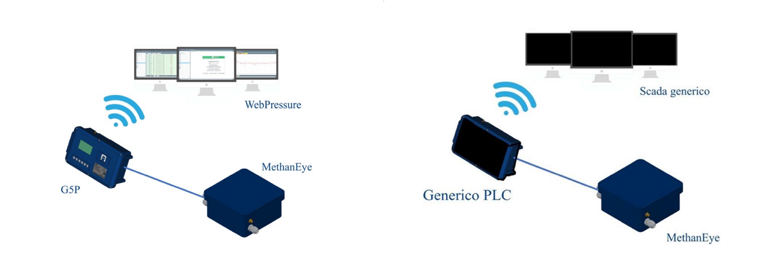
MethanEye can easily integrate with existing PLC, G5P Automa and SCADA systems, or operate in stand-alone mode thanks to the integrated modem. This flexibility makes it suitable both for new installations and for the adaptation of existing systems.
Una soluzione per la quantificazione e la riduzione delle emissioni di metano methaneye
Una soluzione per la quantificazione e la riduzione delle emissioni di metano methaneye (1)

Reducing emissions without compromising the network: GOLEM-ZERO

Measuring and quantifying is essential, but not enough. The reduction of emissions also involves a more intelligent management of operating conditions. GOLEM-ZERO was created precisely to meet this need.

It is a smart regulator capable of dynamically regulating network pressure based on real demand conditions, avoiding overpressure phenomena that contribute to increased leaks. Installable in Plug&Play mode, without the need to interrupt the service; the system is applicable to any regulator model and can be easily integrated into existing NTS offtakes and district governors thanks to custom-designed adapters. In addition, GOLEM-ZERO operates thanks to an integrated intelligence system, reducing the need for manual interventions.


Reducing overpressures without compromising service

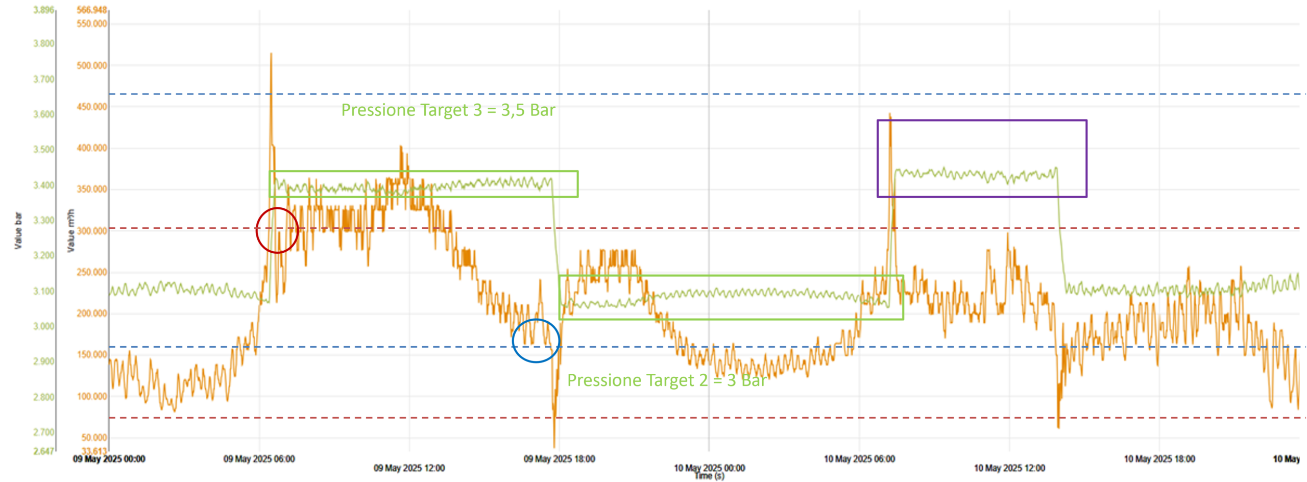
The operating principle of GOLEM-ZERO is based on a flow rate band adjustment. The system divides the network’s operating range into different operating bands, each of which is associated with an optimised target pressure based on demand.

The bands are designed to partially overlap, so as to avoid continuous pressure fluctuations as the flow rate varies. The target pressure is changed only when the flow rate leaves the operating reference band, ensuring operational stability and continuity of service.
Una soluzione per la quantificazione e la riduzione delle emissioni di metano golem zero


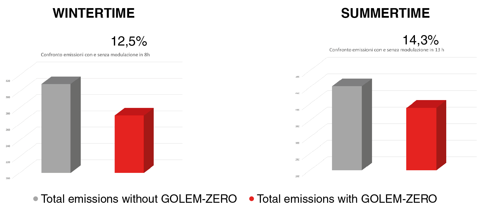
This logic allows GOLEM-ZERO to automatically adapt to different operating conditions — daily, weekly and seasonal — avoiding unnecessary overpressure phenomena. The benefits are also reflected in environmental terms: studies based on models developed by GERG (European Gas Research Group) show reductions in emissions of up to 12.5% in winter and up to 14.5% in summer.
A concrete answer to a real problem

The synergy between MethanEye and GOLEM-ZERO represents a concrete response to the challenges posed by EU Regulation 2024/1787. Not only does it enable methane emissions to be monitored, quantified and reduced, but it also provides operators with a tool to deal with an evolving regulatory environment with greater awareness, reducing operational risk and supporting future compliance.

  For more information, download the White Paper   I want information

 

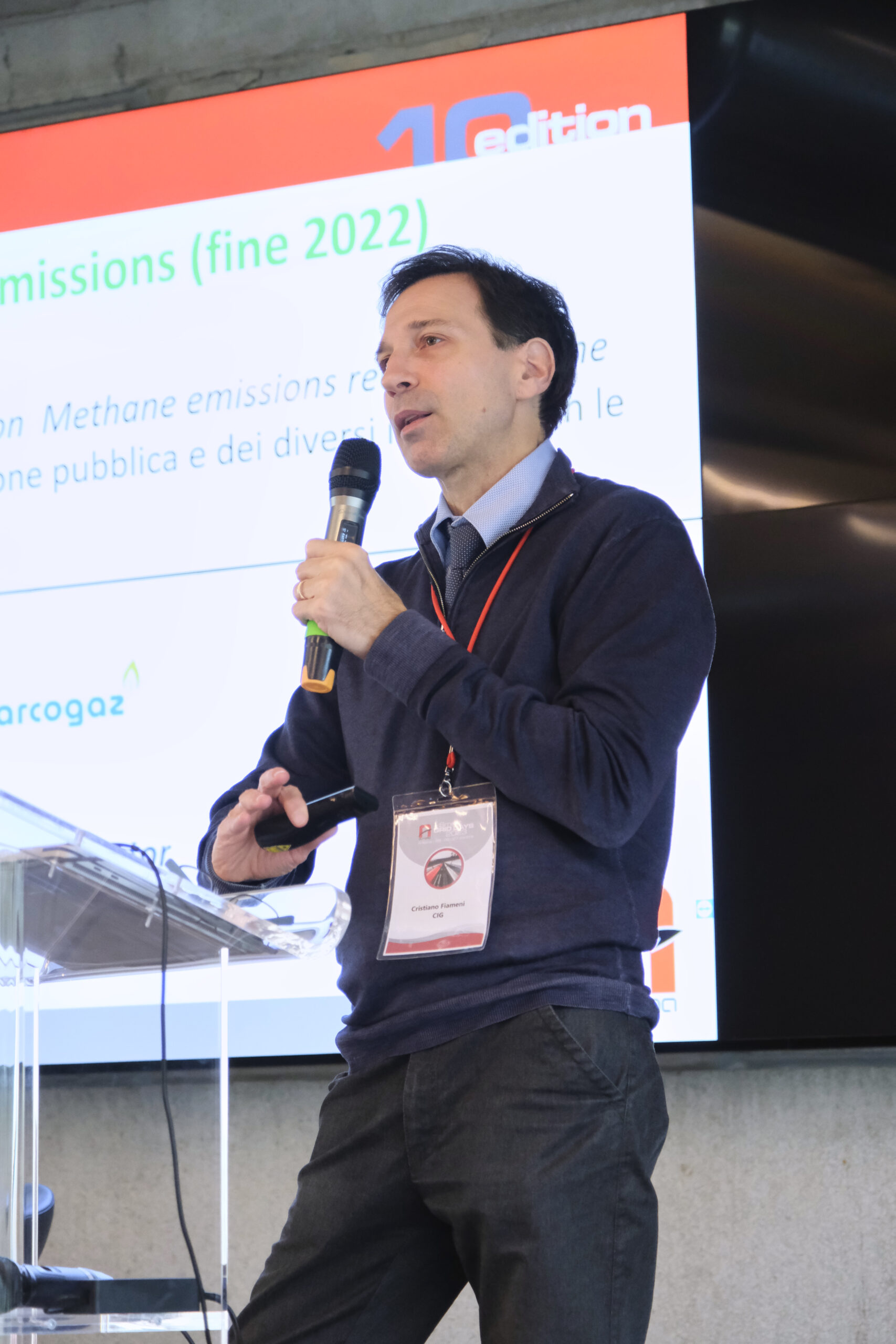
By Cristiano Fiameni, Technical Director of the Italian Gas Committee
From the speech ‘Methane emissions: the evolution of legislation’
SMART GRID DAYS 2025, 8 – 9 October 2025.

Methane emissions is a topic we cannot avoid addressing, since EU Regulation 2024/1787 on the reduction of methane emissions in the energy sector has been published. We will therefore see the guidelines along which the activity has developed during 2025 and the prospects we can glimpse in the application phase of this Regulation, which is particularly complex.

The operational challenges of the Methane Emissions Regulation

The Regulation was published in July 2024 and came into force on 4 August of the same year. It is important to emphasise this date, because a series of important deadlines originated from that moment.

This measure is particularity invasive. Indeed, it not only sets the objectives but  also maps out the path, leaving little room for the technical sector and causing difficulties from an operational point of view, as it has strong limitations on the modalities that inevitably clash with the practical needs of operators.

As already mentioned, the main objective of the introduction of the Regulation is to reduce emissions; to this end, they must be researched, found, quantified, verified and repaired. This applies to the entire gas chain: transport, distribution, storage and regasification.

On the one hand, covering the entire supply chain is positive. But on the other hand, as the latter is very diverse, the tools to be used should be adapted to each portion of the supply chain. In reality, however, the regulation is one-size-fits-all, and provides a single way of operating regardless of whether one has to work on a regasification plant or on an urban network spread over a city of millions of inhabitants. The requirements and methods of intervention are therefore the same, and this is the crux of the matter from which the critical issues in the application of Regulation 2024/1787 arise.

The fulfilments of the Regulation

Since the entry into force of the Methane Emissions measure, there are several obligations: some are the responsibility of the Member States, while others are the responsibility of the operators or the Commission.

With regard to Member States, several European countries have not yet completed the process of appointing the competent authority. Italy, on the other hand, has already submitted a draft law and made available official e-mails from the MASE (Ministry of the Environment and Energy Security) to which operators can refer for communications.

As mentioned, the operators involved also have certain obligations: in August 2025, for example, they had to submit the first leakage research report (LDAR) on the previous year, and they also had to quantify emissions, using generic emission factors. This meant that even more precise assessments could be made, but the minimum required was the use of literature values of emission factors applied to one’s assets.

The Ministry reported that most operators were able to fulfil this obligation. There will be problems in the coming months, however, because from February 2026 operators will have to submit another report using emission factors specific to their asset. This requires operators to perform an important activity of evaluating their assets, and how to relate this data to factors that have a realistic place in their system. This is not easy so there will be difficulties.

In 2027, however, operators will have to submit a report quantifying emissions from one’s assets and verifying the measures taken on the ground against the results in the atmosphere, i.e., reconciliation. This is a rather ambitious challenge for the sector, given that the Regulation presented the requirements without all the necessary tools being available yet.

The supporting technical standards

Another issue to be taken into account is the instruments, i.e. the technical standards supporting the measure. Indeed, the Regulation not only stipulates that there must be technical standards to support this activity, but also provides that these standards can be recognised by the European Commission as implementing instruments. The body that draws up the standards is the CEN (European Committee for Standardisation), in which several European countries, including Italy, participate.

However, there are critical aspects to this path. The first aspect is that a specific request from the Commission (standardisation request) is needed to draw up standards. This request was submitted in 2024 and it took some time to reach a conclusion. The latest news tells us that the technical phase of discussions between the Commission and CEN has been concluded, and that the contract will be signed shortly. Since the contract provides three years to draft the standards, we could have them by the end of 2028. Therefore, we are faced with an asymmetry: the stricter requirements apply from 2027 onwards, while the standards will perhaps come into force at the beginning of 2028. This represents the first problem.

The second problem is that the Regulation has taken on the honours and burdens of precisely determining technical requirements as well, and this has become an obstacle. Indeed, the Regulation requires the Commission to publish a delegated act specifying the MDLs (Minimum Detection Limits) for technologies and providing guidance on the limits for pre-localisation. The point is that these values have not yet been defined.

An initial stakeholder consultation document came out in 2025, which was supposed to be the basis for producing a subsequent one. The deadline was 5 August 2025, but it was not met. Therefore, we are faced with a doublecritical issue: the first is related to technical standards that are not available due to delays in the Commission’s issuing of the required documents; the second concerns the practical aspect related to operators. The latter, indeed, have obligations that they cannot postpone, and in order to fulfil these obligations they must carry out activities in the field that require investments in technology and equipment.

It must therefore be considered that there are also investments made ‘in the dark’, hoping that industrial best practices will be considered in this delegated act and that consequently these investments will be recognised as valid. Unfortunately, it is a time of great uncertainty.

The work carried out so far and the next steps expected

What have we done in the meantime? The CIG, through the experts made available by its members, participated in the activities and contributed by bringing the Italian position to the European tables.

At European level, it is worth noting the contribution of Marcogaz, the international non-profit association representing the European gas industry, which has produced guidelines for the application of the Regulation. These guidelines provide guidance on the main aspects and introduce two useful elements for operators. Firstly, they provide illustrative diagrams of the process to be followed in accordance with the Regulation. In addition, they include a chapter on the cost-benefit analysis of the activity carried out: the repair of the leak must not cause more environmental damage than the leak itself.

This initial document provides some general guidelines that allow us to assume that this concept will be included in the standardisation request that the Commission will submit to CEN. If this is the case, CEN will be able to develop a chapter dedicated to guidance for operators on cases where the effort is not worthwhile. Especially for those working in the distribution sector, having such indications is very important because the numbers involved are really significant.

Marcogaz in 2024 published guidelines on the Venting & Flaring part and commented in detail on the first consultation paper on the limits proposed by the Commission, which were considered unrealistic for some applications. Indeed, there are both established and modern technologies, but it must be ensured that there is no one way to operate: a neutral approach must be taken in order to achieve the desired result.

In view of the Commission’s request, the CEN decided not to publish the draft on MRV (Monitoring, Reporting, Verification), which started in 2022, but to use it as a technical basis for developing the ongoing standards. The European Technical Committee CEN/TC 234 is developing, in parallel, three standards to support the implementation of the Regulation:

  • The first is on the quantification of leaks and associated reporting – MRV (Art. 12).
  • The second is on LDAR (Leak Detection and Repair) (Art. 14).
  • The third is on Venting & Flaring (Art. 15, Art. 16).

Thus, CEN has already prepared drafts which, in order to be developed and sent to public enquiry, require the two documents we mentioned in the previous paragraphs: the standardisation request and the delegated act.

Lastly, the CIG worked on the drafting of a national guideline that, in compliance with legal requirements, would lead to the practical application of the Regulation for the distribution sector, trying to ‘hold together’ the obligations of the provision with the prescriptions of ARERA (Italian Regulatory Authority for Energy, Networks and Environment).

The activity was completed in November 2025 and was preliminarily presented to the MASE.

The Italian Gas Committee, established in 1953, aims to improve safety and efficiency in the use of combustible gases. In 1960, it joined the UNI, the Italian national standardisation body, thus becoming the official Italian body for standardisation in the fuel gas sector.

As an association comprising institutional and non-institutional members, the IGC covers with its members the entire supply chain, from gas import to transport, distribution, storage, utilisation, equipment, devices and installations.

Biogas upgrading to biomethane is a technological process that converts biogas produced from renewable sources, such as livestock manure or agricultural biomass, into biomethane, suitable for injection into the natural gas distribution network.

It is a complex purification process, which aims to increase the quality of biogas by removing impurities and CO₂ present in it. The resulting methane is then collected, compressed and called biomethane.

The biomethane generated through the upgrading process is chemically comparable to natural gas and can be injected into existing infrastructure and used in conjunction with other sources to meet energy demand.

At present, biogas production and its conversion into biomethane are still much lower than the injection capacity of the NTS offtakes.

Furthermore, this quantity varies depending on the circumstances characterising both the production and conversion processes.

Currently, the gas distribution manager is required to guarantee priority injection to the biomethane producer. Therefore, the system must always feed biomethane into the network when it has biomethane suitable for injection, which has priority over other natural gas plants connected to the same network.

However, there are different scenarios that can occur during the injection process. What can happen?

Possible scenarios during biomethane injection

When biogas is produced and the upgrading plant maintains a regular supply of biomethane in both quantity and quality, ideally there are no obstacles to the normal operation of the injection system.

But situations can also arise that lead to critical issues, such as:

  • The pressure measured at the regulator inlet tends to increase progressively due to the increase in biomethane production in the upgrading system. In this case, the risk is that an overpressure phenomenon may occur.
  • The flow rate of the upgrading system is higher than the maximum permissible flow rate of biomethane, meaning the producer injects more biomethane than contractually agreed with the gas distributor. This condition does not normally entail risks for the safety of the system but has economic consequences for the producer who incurs sanctions or penalties provided for in the contract for exceeding the emission limits.
  • The biomethane coming from the upgrading system does not have sufficient pressure to exceed the network pressure, which in this case is high due to low demand or a backpressure condition. Even if production is regular, network pressure hinders injection, leading to possible system shutdown.
  • The network pressure undergoes a temporary increase due to the decrease in consumption. Under these conditions, the network pressure could reach the regulator setpoint, thus causing the injection to block.
  • The biomethane coming from the upgrading system does not meet the required quality parameters.There is therefore a problem at the systems/equipment level (safety alarms, prevention alarms, faults, power outages) which forces the plant to stop.

The AUTOMA solution to overcome critical scenarios

To avoid the problems associated with the critical scenarios we have just seen, at AUTOMA we have designed and built a system capable of

optimising the injection of biomethane into the natural gas network and guaranteeing priority injection to the producer, regardless of hourly fluctuations in production, flow rate, pressure and network demand.

This is the GOLEM-ZERO dynamic regulation system, which combines advanced electronics with an electromechanical actuator. GOLEM-ZERO moves the adjustment screw of a standard pneumatic pressure regulator, transforming it into an intelligent regulator.

GOLEM technology is based on a mechanically coupled servomechanism that interacts directly with the pressure regulator pilots, supported by an advanced electronic system. Thanks to the intelligence built into the system, GOLEM-ZERO can operate in autonomous mode and dynamically adjust based on actual boundary conditions, thus reducing the need for manual intervention on site.The system is applicable to any regulator model and can be easily integrated into existing NTS offtakes, thanks to custom-designed adapters.

Power can be supplied via the electricity network, but also via a photovoltaic system. In addition to the safety controls implemented at the logic level, during the development phase — both in the laboratory and in the field — mechanical and electromechanical safety systems were introduced to prevent issues caused by possible jamming of the pilot adjustment screw and, more generally, with the implemented control logics.

The system can be operated manually or remotely via any SCADA software or through WebPressure (a suite developed by AUTOMA specifically for the sector). It operates in fully automatic mode, dynamically adjusting the regulator set-point according to predefined control logics. The GOLEM-ZERO system communicates locally with the GOLIAH5P (G5P), i.e. an AUTOMA RTU, or with any PLC/RTU via Modbus protocol on RS485 port.

Thanks to GOLEM-ZERO, biomethane injection management takes place in real time, remotely and automatically. The system optimises day-to-day operational activities while ensuring a long-term success perspective for the plant.

In the presence of a demand for gas from the network, the downtime during which it is not possible to inject biomethane due to fluctuations on the production side is normally around 10 – 12% of the annual hours. Thanks to GOLEM-ZERO, these interruptions decrease by 70 – 80%, allowing for the injection of up to 6 – 8% more biomethane over the course of the year.

Furthermore, unplanned but necessary field balancing interventions to ensure injection priority decrease by up to 35%, which translates into lower operating costs.

AUTOMA designs and produces innovative, Made in Italy hardware and software solutions for remote monitoring and control in the Oil, Gas and Water sectors.

We were born in 1987 in Italy, and today over 50,000 AUTOMA devices are installed in more than 40 countries around the world.

Do you want to ensure a priority and uninterrupted biomethane injection into the network, with maximised uptime?

Contact our team without obligation and we will tell you what we can do to optimise infrastructure operations and control.

From the speech “The evolution of the distribution network”
SMART GRID DAYS 2024, 18 — 19 September 2024.

Centria is a city distributor that operates in 16 mainly Tuscan provinces (Italy), but with some excursions to Puglia and Umbria, and has collaborations with other companies in the Grosseto area (Lazio region). It has about 6,000 km of gas pipelines, managed mainly at medium and low pressure, and more than 400,000 customers.

Centria has always wondered if it is possible to make a contribution to decarbonization. Today, cathodic protection also asks itself this question. The distributor would like to make his work more efficient and advanced, despite offering an energy-intensive service.

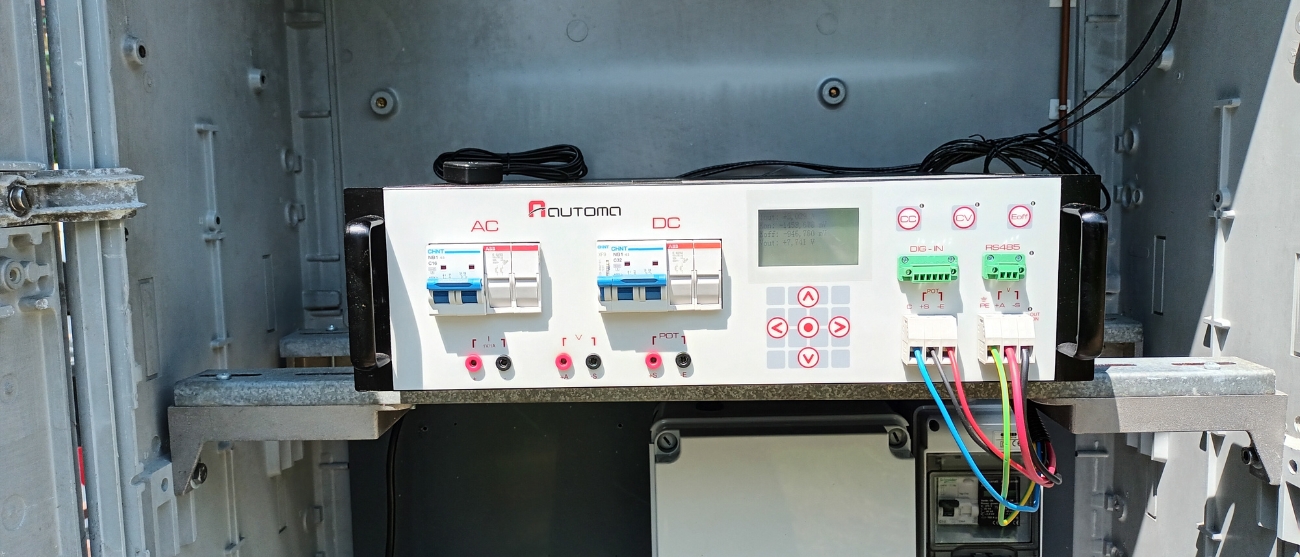
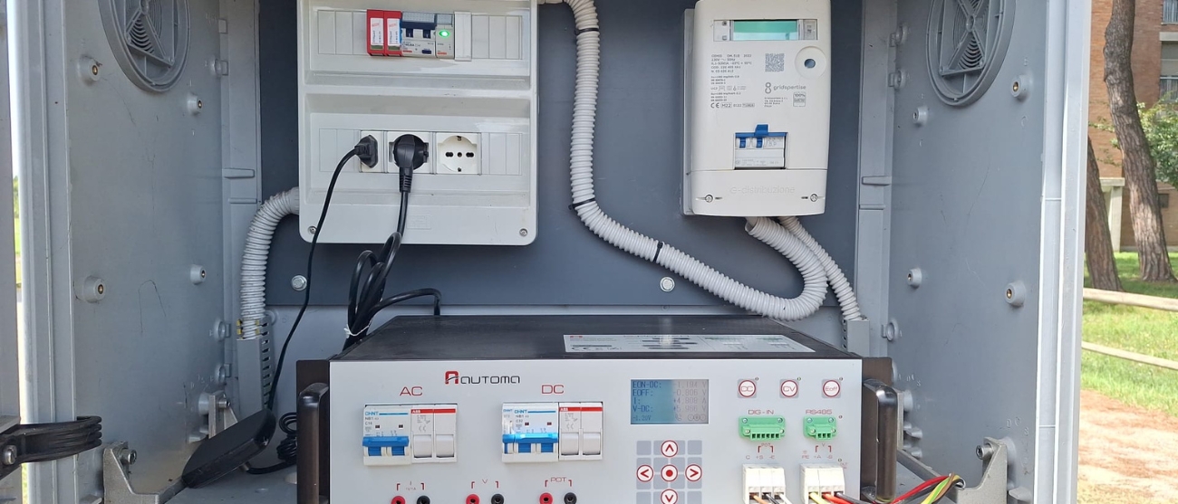
In this case, technology comes to the aid: the case studies thatwe present are two examples of interventions carried out on the cathodic protection of two city distribution systems using impressed current. In both cases, an AUTOMA G-POWER device was installed to replace the rectifier previously in operation: in the first case, G-POWER replaced the only rectifier in the system, while in the second it replaced one of the two rectifiers.

Case 1: The starting situation and the AUTOMA solution

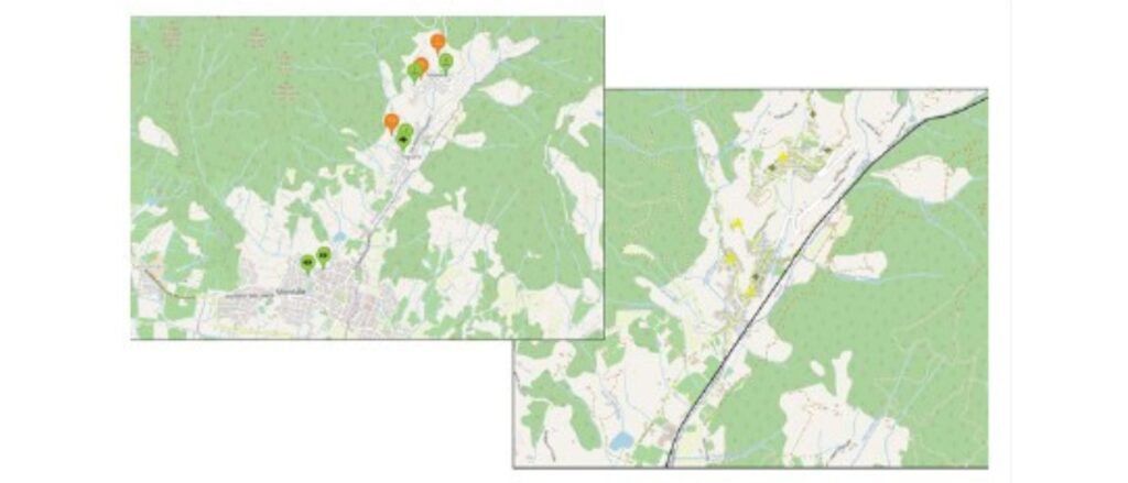
The system is located in the town of Montale, in the province of Pistoia. It is equipped with 13 km of pipes, of which about 50% medium pressure and 50% low pressure, and a single cathodic protection rectifier, operating at constant potential, with base current.

The adjustment was made with the Eon potential because it was the only way that that rectifier could work, that is, with a potential of -2.8 V corresponding to about an Eoff of -1.1 V. The base current was 1.30 A that had to be constantly supplied even in conditions of potential lower than that required. The current supplied varied a lot because it is a very interfered system. The variation ranged from 7 A to 12 A, with an average value of about 10.5 A.

The kilometer extension of the system is quite large, so you start from a fairly flat area and arrive at the first hills. As can be seen from the first image, the pipes are fairly distributed. While in the second image you can see the dislocations of the characteristic and remotely monitored measurement points.

Verso l'efficienza e l'automazione intelligente nella protezione catodica case study pistoia centria automa territorio

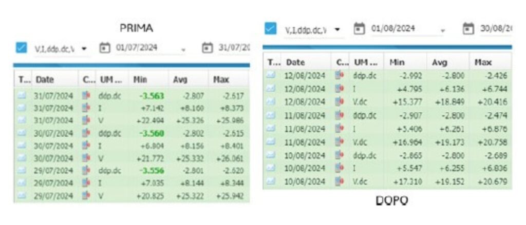
From the remote control data before replacing the rectifier, you can actually see that the current has values between 7 and 12 A, with an average value around 10 A.

We removed the rectifier that was previously in operation and replaced it with AUTOMA’s G-POWER. After turning it on, we reset the parameters that were used with the previous rectifier, namely constant potential regulation with an Eon value of -2.8 V. We chose to use G-POWER with the same setting as the previous rectifier to check if there were any operating differences under the same conditions. In the table you can see the new data returned.

Verso l'efficienza e l'automazione intelligente nella protezione catodica case study pistoia centria automa tabella

So we haven’t changed either the adjustment system or the system or its surrounding elements. Right from the first ignition we had a fairly unexpected surprise: the current was reduced by almost 25%, going from an average value of 8 A to just over 6 A.

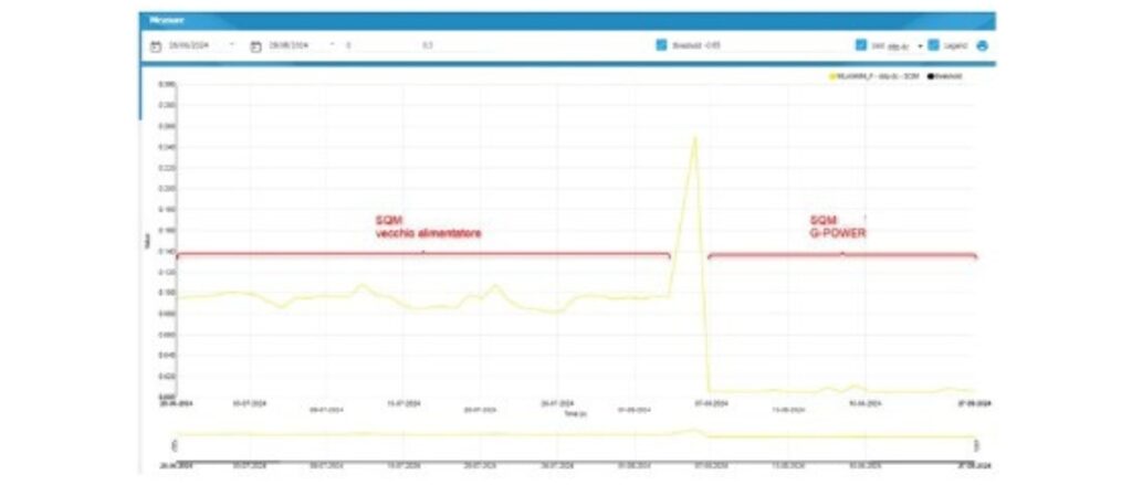
We asked ourselves why and with AUTOMA we did a bit of analysis on these measures. Let me start by saying that the amount of time we had for analysis was short: the rectifiers were put into operation in the month of July-August 2024, and what you see are preliminary data about two months after the start of the system, in September 2024. But these checks give us hope that we have at least taken the right path.

Verso l'efficienza e l'automazione intelligente nella protezione catodica case study pistoia centria automa grafico

Why was there this reduction in power? Going to see the measurements, we noticed that the only thing that has really changed in the data coming from the remote control is the average square deviation from the adjusted value. The difference is important: we went from 0.2 to 0.02. This variation indicates that the regulation is much more stable over time, which translates into a smaller variation in the current supplied and therefore in a more stable and lower current than it was initially.

Case 2: The starting situation and the AUTOMA solution

The second system we are talking about is in the town of Sesto Fiorentino (Florence), where Centria has two rectifiers. Of these, only one was replaced during this test because we wanted to see the interaction of G-POWER with other rectifiers.

Both starting rectifiers operated at constant potential and were both adjusted to -2 V of Eon potential, corresponding to about -1.1 V of Eoff potential. The total current was 13 A, divided more or less equally on the two rectifiers.

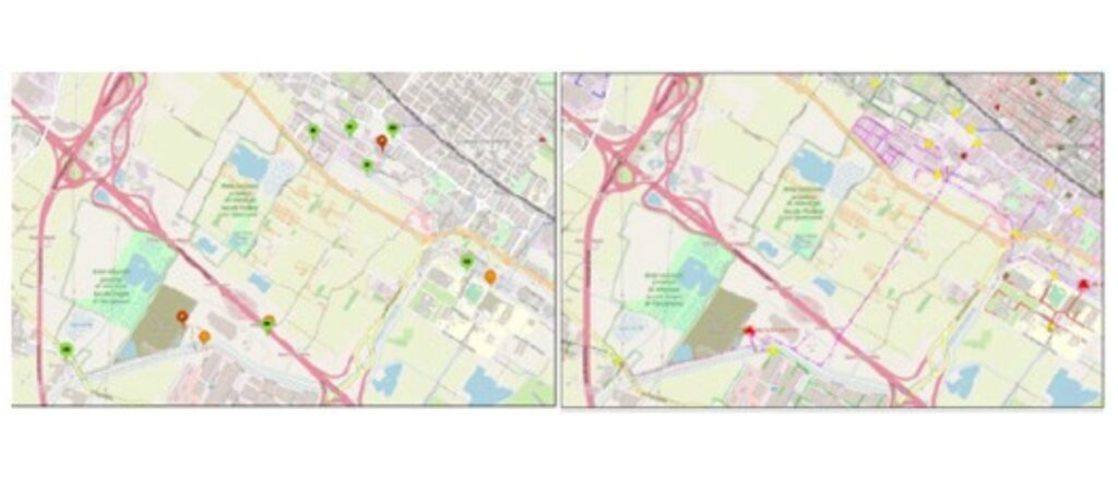
We have about 11 km of mainly medium-pressure network, so we had networks in the fourth species and networks in the sixth species (0.5 bar and 5 bar) in the city center of Sesto Fiorentino, which is a very interfered area with the presence of a railway.

Verso l'efficienza e l'automazione intelligente nella protezione catodica case study sesto fiorentino centria automa

Only the rectifier that has been replaced has been set to make the adjustment work on the Eoff potential. We did several tests and then decided to adjust the Eoff potential no longer to -1.1 V (as it was set on previous rectifiers) but to -0.95 V.

At this point, the second rectifier was turned off because G-POWER was more than enough to protect the entire connected structure. First, the two rectifiers shared the current load (about 6 A/6.5 A each), but with the introduction of AUTOMA’s G-POWER one of the two was completely stopped, while the other supplied about half of the current that was previously supplied in total by two rectifiers.

The reduction in current in this case was significant, by 50%, both for the adjustment stability of the rectifier and for the lowering of the Eoff potential. Achieving these results is an important goal for a company with environmental certification.

Let’s mention the ease of installation of the AUTOMA device. G-POWER has also incorporated the data logger, and therefore all its functions: cyclic switch, remote controls, transmission system. It is enough to bring it on site and attach some cables to make it immediately operational, while for the previous rectifiers it was necessary to do a wiring that perhaps in some cases required half a day to connect all the devices. Even a quick installation translates into better efficiency for the company.

In conclusion, with AUTOMA’s G-POWER we have a product that has better regulation and stability in its operation, which is certainly also due to the fact that it has very new electronics. Clearly, being a new product, its potential is still to be explored. But for the moment we can say that, in addition to a significant simplicity of installation, it also offers a great advantage in the possibility of adjusting on the local Eoff potential.

AUTOMA designs and produces innovative and Made in Italy hardware and software solutions for remote monitoring and control in the Oil, Gas and Water fields.

We were founded in 1987 in Italy, and today more than 50,000 Automa devices are installed in more than 40 countries around the world.

Do you want to know the cathodic protection advantages you could have with the AUTOMA monitoring system?

Contact our team without obligation and we’ll tell you what we can do to optimize your infrastructure control.

From the intervention “Cathodic protection. Commissioning of an impressed current system in the presence of non-stationary interference”
SMART GRID DAYS 2024, 18 – 19 September 2024.

The INRETE distribution group, part of the Hera Group, is involved in the distribution of gas and electricity in Emilia-Romagna and Tuscany.

The case study we present concerns the commissioning of a cathodic protection system with impressed current for a distribution structure in the presence of non-stationary interference. Due to the morphology of the structures, this type of setup is extremely dynamic. We will see how the use of AUTOMA technologies, applied to regulation (with a G-POWER installed as the rectifier closest to the interference) and measurement techniques (a G4C-PRO device installed on the second power supply and a G4C-PRO with SOLAR BOX installed at the remote measurement point) can contribute to the efficiency of our plants, regulating them in a more effective way.

The starting situation

The system we are examining is a portion of a distribution plant in an urban neighbourhood where there is an interference caused by the nearby electrical substation of a direct current traction system.

The network, laid in predominantly sandy soil, is protected by two impressed current systems and served by a unidirectional drainage system. The architecture of the grid (qui credo ci vada grid) is mainly meshed, with an extension of about 24 km, and a surface area of slightly over 10,000 m².

Everything begins with the decommissioning of the unidirectional drainage system.

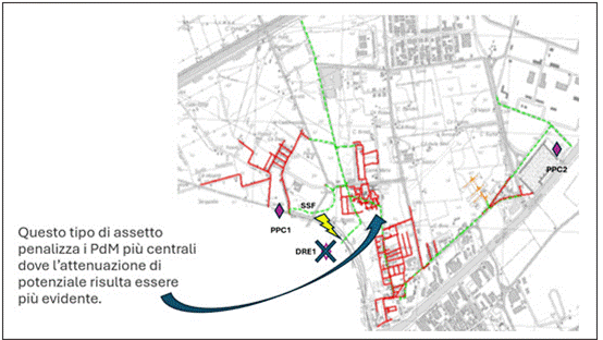
The new setup started in 2019 with: determination of the electrical state; assessment of the variability of the electric field; regulation and thus balancing of the electrical system. The new morphology places the two rectifiers (the two diamonds you see in the image – next page) in positions that are very off-center with respect to the detected interference.

Gestione smart della protezione catodica a corrente impressa

This means that the urban area closest to the interference registers very evident potential attenuations. We therefore decide to design an impressed current system, determining the variability of the electric field and analysing the most anodic areas, therefore the most suitable for this implementation.

The impressed current system

In October 2022 we realised the new impressed current system. Consequently, we also moved on to the implementation across the entire network of new measurement points with polarisation probes. In November 2022, we realised the new electrical setup which, indeed, places the newly designed rectifiers closer to interference.

Following the new commissioning and the variation of monitored electrical parameters – in compliance with UNI11094 – we reclassified all measurement points. We consequently decided to redo a new commissioning of the entire system, adhering to UNI EN ISO15589-1, starting from a preliminary investigation:

  • Verification of the integrity of the disconnection.
  • Verification of all wiring.
  • Variability of the electric field.
  • Start-up of the system with a checklist of all installations and related safety devices.
  • Start-up of the installations with electrical state settings.
  • Verification of electrical continuity.
  • Rebalancing both the installations and the resistors on our network.
  • Measurements of currents on the joints.

Consequently, we proceeded to the complete mapping of the entire system.

Me moved on with the reclassification of measurement points, cartography update, and – a frequently forgotten step – the collection of all these data in a commissioning report, where we recorded the reference values of the electrical state of our system, in accordance with the ISO standard, for comparison with future measurements.

Our remote monitoring system provides us with the opportunity to report for each individual measurement point its set point following calibration, directing it towards the balancing of the system. As can be seen in the image, this means that, in case of exceeding the set point, the monitoring system creates an anomaly line, from which an intervention order can be generated.

Gestione smart della protezione catodica a corrente impressa anomalia

A current impressed system is particularly dynamic and the initial interventions, in addition to the aforementioned decommissioning of the drainage system, have provided the opportunity to improve the system, reducing the current density from 2.7 mA/m² obtained with the first setup in 2017 to about 1.0 mA/m² in 2023.

The AUTOMA solution to the interference problem

All these activities have certainly mitigated the issues present in the system, but without resolving the interferences that interact with the rectifier control system.

Fortunately, technologies are on our side and the adoption of the technique of measuring the Eoff potential (Instant-off) on the most interfered rectifier will prove to be a wise choice.

The new rectifier, the G-POWER by AUTOMA, has given us the ability to control the system directly based on the Eoff Value, which is the value corrected for the IR component, allowing its PID controller to be less sensitive to potential fluctuations.

Gestione smart della protezione catodica a corrente impressa G-POWER by AUTOMA

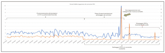
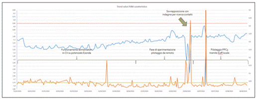
This is particularly noticeable in the standard deviation of the current output from the rectifier. In this first setup, where both rectifiers operated at variable current, it is possible to see how variable the standard deviation was throughout the day.

In the subsequent testing phase, we linked the control of the rectifier closest to the interference to a remote E-probe even closer to the interference itself, while the other impressed current system was set to constant current (the visible spikes in the image are due to maintenance activities).

In the final setup, where the interfered rectifier was set to a local Eoff potential, a flattening of the root mean square deviation can be observed. With this configuration we have effectively halved the standard deviation of the current, a factor that, although less evident but equally interesting, is also noticeable in the root mean square deviation of the DDP E-probe detected at the most characteristic point of our system. Even in this case, there is an almost halving of the value in the phase of controlling the rectifier via local Eoff, which manages to operate at less electro-negative E-probe potentials.

Gestione smart della protezione catodica a corrente impressa G-POWER by AUTOMA

AUTOMA designs and produces innovative hardware and software solutions made in Italy for monitoring and remote control in the Oil, Gas and Water sectors.

We were born in 1987 in Italy, and today over 50,000 Automa devices are installed in more than 40 countries around the world.

Do you want to know the advantages for the safety of your networks that you could have with the AUTOMA cathodic protection monitoring system?

Contact our team without obligation and we will tell you what we can do to optimize your infrastructure control.

Cathodic protection has always been one of the fundamental strategies to slow down the corrosion of underground metal structures, such as pipelines. However, until recently, the techniques adopted to verify its effectiveness were often limited to manual, punctual measurements and not adequately representative of the entire system, especially in the presence of interference.

Today, thanks to the introduction of advanced technologies, big data and artificial intelligence, cathodic protection monitoring is undergoing a real revolution.

Traditionally, it was based on surveys carried out at certain points in the network: operators collected periodic readings of the ON potential and, based on these measurements, adjusted the setpoints of the rectifiers. This method, however, showed significant limitations: the values detected represented only an instantaneous measure and did not take into account fluctuations during the day or external interferences, such as stray currents generated by nearby infrastructures.

With the evolution of networks and the increase in interference, it was understood how necessary a paradigm shift was. This is how AUTOMA created the idea of an intelligent management of the cathodic protection system (Smart CP System): an ecosystem capable of monitoring every point of the network in real time, automatically regulating the current supplied by the cathodic protection rectifiers and predicting critical issues before they turn into concrete problems.

AUTOMA’s Smart CP System is an innovative approach that combines digital technology, data analysis and artificial intelligence to optimize the operation of the entire cathodic protection system in real time.

From analog to digital: the Smart CP System, the AUTOMA revolution

In the past, as we said just above, operators performed spot surveys on specific ‘points’ of the network, manually measuring the ON potential. This data was used to configure rectifiers, often with a high safety margin to compensate for measurement uncertainty and fluctuations over time. The result? Often more current was supplied than necessary, with consequent energy waste and, above all, the risk of overprotection and damage to the coatings.

In addition, the increase in ground interferences — due to stray currents, electric railway lines, industrial plants or power lines — has made the ON potential less and less reliable as the only reference parameter, or at least considerably more complicated to interpret.

The Smart CP System was created to overcome these limits. It is a centralized and intelligent management platform that continuously and dynamically controls all components of the cathodic protection system: rectifiers, measuring points, electrodes, and remote control devices. Its objective is twofold: to keep the IR-free protection potential stable and to optimize the output current of the rectifiers, avoiding waste and malfunctions.

Among the system’s key technologies:

  • RDU (Remote Datalogger Unit) installed at every critical point of the network, able both to function as a remote datalogger and to transmit measurements of the On and IR-free potential in real time.
  • Smart rectifiers, capable of working in a new automatic mode based on IR-free potential.
  • Remote control of the rectifiers, with the possibility of modifying the operating parameters from a central platform.
  • Adaptive algorithms that analyze historical data, seasonality, environmental conditions, and network status to anticipate and solve problems before they occur.

The heart of the Smart CP System is the new generation of smart rectifiers developed by AUTOMA, capable not only of operating in traditional modes, but also of working on the basis of IR-free potential. Connected to a coupon, these rectifiers constantly measure the real potential of the structure and adapt the current supplied to keep it stable.

All this is made possible thanks to a digital platform that integrates data analysis, predictive algorithms and remote control.

Not only that: currently, rectifiers in automatic operating mode base their adjustment on local feedback, but they must guarantee effective protection over the entire extension of the protected structure. For this reason, the possibility of identifying the most critical point (or points) of the network, equipping it with an RDU that allows more frequent communication during the day and connecting this point to the rectifier so that it works and varies its current supply based on the measurements taken by the critical point, opens up a completely new and much smarter opportunity to manage cathodic protection: the possibility of guaranteeing in every moment an effective protection of the entire structure to be protected, while at the same time delivering the minimum current necessary to achieve this purpose.

Scalable configurations and intelligent algorithms

The Smart CP system is extremely flexible and can be configured in different ways, depending on the complexity of the infrastructure (number of rectifiers and critical reference points identified):

  • One to one: a rectifier controlled by a remote measuring point.
  • One to many: a rectifier controlled by multiple critical points, with an algorithm that identifies the dominant point for regulation.
  • Many to many: multiple rectifiers interact with a network of measurement points, with an intelligent balancing of the currents.

There are two main approaches to control algorithms:

  1. Time-based: the platform interrogates devices at regular intervals and adjusts rectifiers based on predefined thresholds.
  2. Event-driven: each measurement point actively communicates to the platform when it detects a significant deviation, triggering immediate action.

Concrete benefits

The introduction of the Smart CP system brings tangible advantages:

  • Reduction of energy consumption, thanks to a more precise regulation of the current.
  • Longer anode life, avoiding overprotective conditions, and generally delivering more current than necessary.
  • Proactive corrosion prevention, thanks to the real-time view of the network status.
  • Lower maintenance costs, with targeted and data-based interventions.
  • Greater sustainability of the entire infrastructure system.

The first field applications confirm the effectiveness of the approach. The Smart CP system is not only a natural technological evolution, but a real paradigm shift: from static and reactive protection to intelligent, predictive and adaptive management of critical infrastructures.

AUTOMA designs and produces innovative and Made in Italy hardware and software solutions for remote monitoring and control in the Oil, Gas and Water fields.

We were founded in 1987 in Italy, and today more than 50,000 Automa devices are installed in more than 40 countries around the world.

Do you want to know the security advantages of your networks that you could have with the AUTOMA cathodic protection monitoring system?

Contact our team without obligation and we’ll tell you what we can do to optimize your infrastructure control.