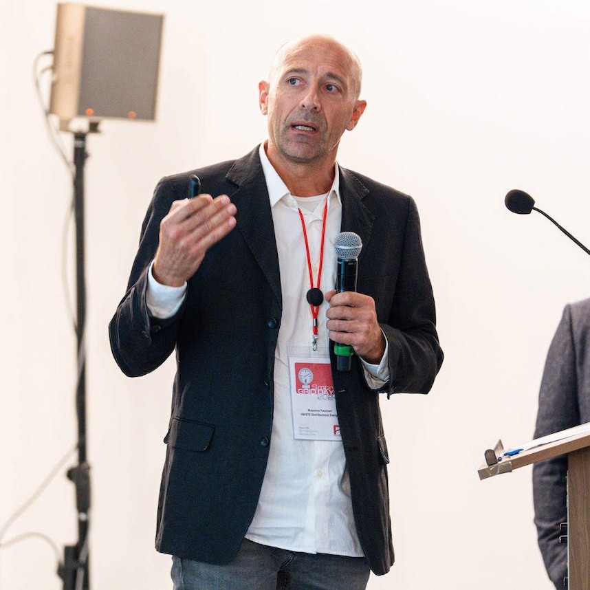
By Lorenzo Spisni and Massimo Tassinari
Technical advisors for cathodic protection at InRete Distribuzione Energia
From the presentation at SMART GRID DAYS 2025, October 8 – 9, 2025.
In the past, we all started from the EON potential data. Then, about ten years ago, we had access to a potential probe that could provide us with additional information. Over time, we discovered that the potential probe could detect the Esonda potential value, coupon current values (Icoupon), and, as we approached the goal of reducing ohmic drops on the potential value, the probe allowed us to obtain EOFF to reach the so-called “free of ohmic drop potential”.
The experience we have carried out on an electrical system is one that gathers a lot of information: we will obtain EOFF measurements on the pipeline and the values of EOFF on coupon. In summary, I would say measurements “with two faces”, as comparing the EOFF measurements obtained with the two techniques proposed by the standards, the data will be conflicting: some data will be compliant and others that probably no one will ‘like’.
Contradictory or ambiguous EOFF values point the way towards more in-depth investigations: these non-compliant data are not due to the reliability of the potential probe product, but we must find the causes in the pipeline – probe – coupon – ground circuit, not forgetting the presence of oxygen.
We will demonstrate that, despite the collected values being conflicting, there are many other basic conditions that completely exclude the possible corrosion of these pipelines.
The regulations and EOFF
We have definitions both in the standard UNI EN ISO 15589-1 and in the standard UNI 11094. In the latter, two methods for acquiring the EOFF potential are mentioned: directly on the structure with interruption of the cathodic current with a typical delay acquisition of 300 milliseconds or on a plate or probe after opening the electrical connection plate-structure within a maximum time of 100 ms. These techniques are valid for the detailed assessment of the effectiveness of the protection condition.
The technique and utility for testing the electrical system and periodic checks are defined in the standard UNI EN ISO 15589-1 (Appendix A.2.3 – A.2.5 and Art. 7.3 – 12.4.2 and Art. 13.3). Therefore, this information on EOFF is valid both in technical scope (how to do it) and in testing (commissioning or testing the protection condition of a system) and regarding the scheduled maintenance of a system (UNI 11094 Appendix A1, A2, A3).
Thus, the experience we bring transfers the cited regulations within a field context, to obtain EOFF information that comes from buried structures.
Below are the techniques adopted for the acquisition of EOFF potential:
- directly on the structure (delay of about 300 ms) EOFF-pipe
- use of potential probe (within a maximum time of 100 ms) EOFF-coupon
- acquisition time of EOFF potential within 2 ms (overprotection),
- acquisition time of EOFF potential within 21 ms,
- acquisition time of EOFF potential within 100 ms (protection criteria).
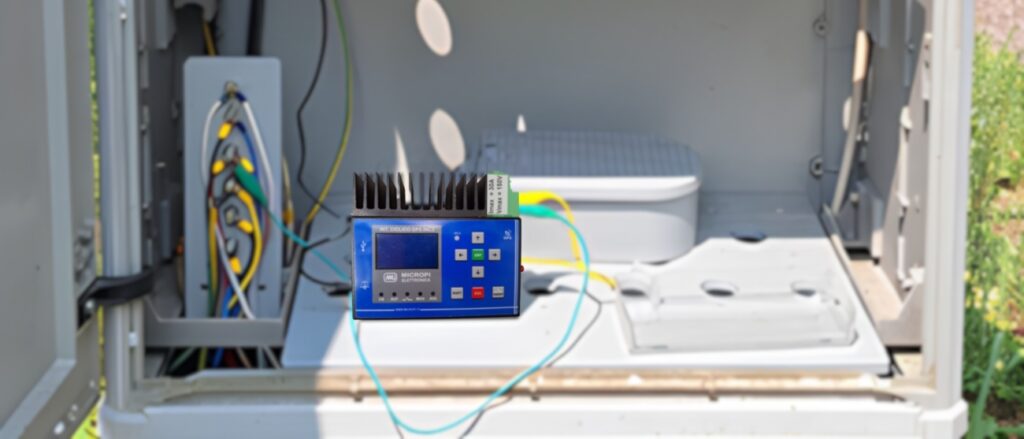
We have identified a suitable electrical system, not subject to interference or with a sufficient non-interference period for data monitoring, where the characteristic measurement points were equipped with potential probes.
The system was identified in a small urban area.
The peculiarity of this system is the presence of a different ground resistivity: in fact, there are areas where, following the reclamation of marshy and lagoon areas, the resistivity is around 7-8 Ω·m, while others, formed on fluvial deposits, present a resistivity in the order of 100 Ω·m.
To explore in detail, it is possible to download the complete case study.
 Technical Coordinator at INRETE
Massimo Tassinari is the technical contact for cathodic protection at INRETE Distribuzione, where he is involved in commissioning and supervising the testing of cathodic protection systems, updating monitoring systems and coordinating ARERA data reporting.